The Matrix layer control (![]() )
is available only for the Corner Plot.
The Corner Plot window starts with one of these in the stack by default,
and you can add a new instance by using the
Add Position Control (
)
is available only for the Corner Plot.
The Corner Plot window starts with one of these in the stack by default,
and you can add a new instance by using the
Add Position Control (![]() ) button
in the control panel toolbar,
or the corresponding item in the Layers menu.
) button
in the control panel toolbar,
or the corresponding item in the Layers menu.
This is the control that supplies all the plots for the Corner plot. Each instance of this control in the stack does plotting for a set of multidimensional points from a single table. The set of points is defined in the Position tab as a column name or expression for each plot coordinate, while the Fill tab provides some controls that can help to fill in in the Position tab. The control can generate multiple different layers from these positions; the Form tab provides many options for what graphics will be plotted based on the positions, and the Subsets tab controls which subsets are plotted and how each one is identified.
This control is a Table Data control as described in Appendix A.4.2.2. That section explains the Subsets tab; the Position, Fill and Form tabs are described in more detail below.
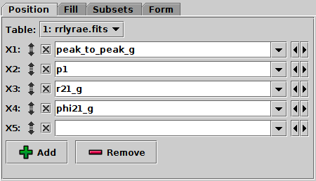
Position Tab of Matrix layer control
To select the quantities that will be plotted against each other, in the Position tab select column names or enter algebraic expressions into the fields marked X1, X2, X3 etc. Grid cells will be plotted for each distinct pair (scatter-plot-like) and single (histogram-like) combination of the specified coordinates.
This position entry panel has a few features not found in the other plot types:
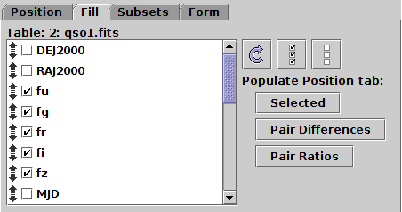
Fill Tab of Matrix layer control
The Fill tab lets you choose columns from the table you are plotting, and use them to populate the selectors in the Position tab. Moving and selecting the columns in this tab does nothing on its own, but if you hit one of the buttons under the Populate Position tab heading on the right, the Position tab, and hence the plot, is updated accordingly. This doesn't do anything that can't be done by filling in fields in the Position tab directly, but it can be a quicker and more convenient way to do it.
The left hand panel shows all the columns in the input table
(as selected in the Position tab).
They can be reordered using the mouse by dragging them with their
Grab Handle (![]() )
and the checkbox by each one can be selected.
The three buttons at the top of the right hand panel also affect this list:
)
and the checkbox by each one can be selected.
The three buttons at the top of the right hand panel also affect this list:
When you have selected the columns you're interested in, you can hit one of the buttons below the Populate Position Tab heading.
A, B, C and D
are selected in the list here,
then clicking this button
will fill in the selectors in the Position tab with
X1=A-B, X2=A-C, X3=A-D,
X4=B-C, X5=B-D,
X6=C-D.
The number of replacement coordinates
(hence the linear size of the grid)
will be N(N-1)/2 so it can end up generating a lot of plots.
This is a rather special-interest option, but it can be handy
for instance when working with sets of correlated parameters
such as source magnitudes.
A/B, X2=A/C, X3=A/D,
X4=B/C, X5=B/D,
X6=C/D.
This could be useful when working with sets of fluxes.
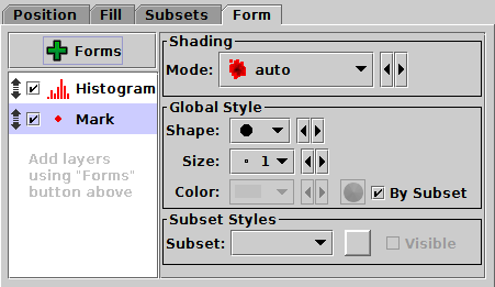
Form Tab of Matrix layer control
The Form tab lets you define how the specified data set is plotted. The stack on the left gives a list of forms currently being plotted, and the panel on the right shows the detailed configuration for the currently selected form.
When first added, the stack contains two entries,
Mark and Histogram.
This gives you a scatter plot on all the off-diagonal grid positions,
and a histogram on all the diagonal ones.
However, there are a number of other forms that you can plot as well
or instead of the simple markers;
two-coordinate plots like contours and linear fits on the off-diagonal
positions, and
one-coordinate plots like KDEs on the diagonal positions.
You add a new form to the stack by
clicking on the ![]() Forms button,
which gives you a menu of all the available forms.
You can remove a form by selecting it and clicking
the Remove (
Forms button,
which gives you a menu of all the available forms.
You can remove a form by selecting it and clicking
the Remove (![]() ) button in the same menu.
You can also activate/deactivate the entries in the stack
with the checkbox and move them up and down with the drag handle as usual.
) button in the same menu.
You can also activate/deactivate the entries in the stack
with the checkbox and move them up and down with the drag handle as usual.
The detail panel of each form depends on the form itself. It is divided into the following panels, though not all forms have all the panels.