7 Newton’s third law
We’re now going to introduce Newton’s third law of motion.
To any action there is an equal and opposite reaction.
The actions of two bodies on each other are always equal and always opposite in direction.
7.1 Example: Normal reaction force
We have already seen this, e.g., in the case of the normal reaction force, as shown in Figure 7.1
- The block exerts a force on the table, the weight \(m \vec{g}\).
- The table exerts an equal force on the block, the normal reaction force \(\vec{N}\).
- The forces are normally drawn acting through the centre of mass.
7.2 Example: Tension in rope
Consider a mass supported by a rope, as shown in Figure 7.2.
- The weight induces tension in the rope which pulls on the support
- The support pulls back on the rope and weight
- These are balanced (i.e., equal and opposite) so there is no acceleration
Consider only the forces acting on the weight when analysing the weight’s behaviour (outlined by the red box in Figure 7.2).
For the weight \[ m\vec{g} + \vec{T} = \vec{0} \]
7.2.1 Example: Bicycle wheel
Consider the bicycle wheel shown in Figure 7.3.
- The wheel exerts a force \(\vec{F}\) against the road.
- The road exerts a friction force \(\vec{f}\) against the wheel, and drives the bicycle forwards.
- \(\vec{f} = - \vec{F}\)
7.2.2 Example: Stepping off boat
Consider stepping off a boat onto the river bank, as shown in Figure 7.4.
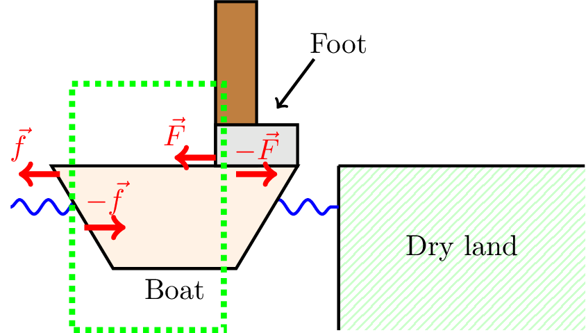
The vertical forces balance, so let’s look at the horizontal forces.
The foot pushes against the boat with force \(\vec{F}\); the boat pushes back with friction force \(-\vec{F}\), accelerating the person towards the bank, and the boat away.
The boat pushes against the water with force \(\vec{f}\); the water pushes back against the boat with drag force \(-\vec{f}\).
The forces acting on the boat are shown in the green box, namely \(\vec{F}\) and \(-\vec{f}\).
If there is insufficient drag, the boat can move greatly during the time taken to step off with the result being disaster!
Ultimately, the person stepping off the boat accelerates to the right, while the boat accelerates to the left. The respective accelerations will depend on their respective masses. This is an example of the two-body problem.
7.2.3 Two body problem and reduced mass
Consider a pair of particles interacting with each other, e.g., through gravity, as shown in Figure 7.5.
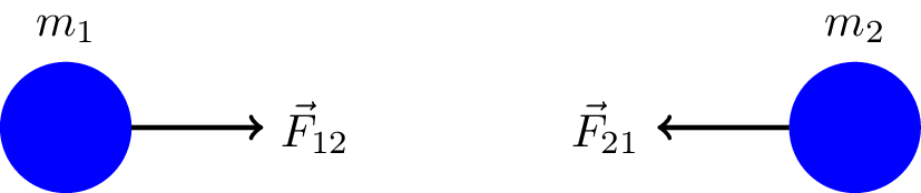
The force on particle 1 due to particle 2 is \(\vec{F}_{12}\). The force on particle 2 due to particle 1 is \(\vec{F}_{21}\).
We can apply Newton’s second law to both particles. \[ m_1 \vec{a}_1 = \vec{F}_{12} \] \[ m_2 \vec{a}_2 = \vec{F}_{21} \]
Then Newton’s third law tells us that \[ \vec{F}_{12} = - \vec{F}_{21} \]
\[ \therefore m_1 \vec{a}_1 = - m_2 \vec{a}_2 \] \[ \vec{a}_2 = - \frac{m_1}{m_2} \vec{a}_1 \]
From a frame in which particle 2 is at rest (Note: this is a non-inertial frame because the particle is accelerating), the net motion of \(m_1\) is (see Figure 7.6) \[ \vec{a}_\text{net} = \vec{a}_1 - \vec{a}_2 \]
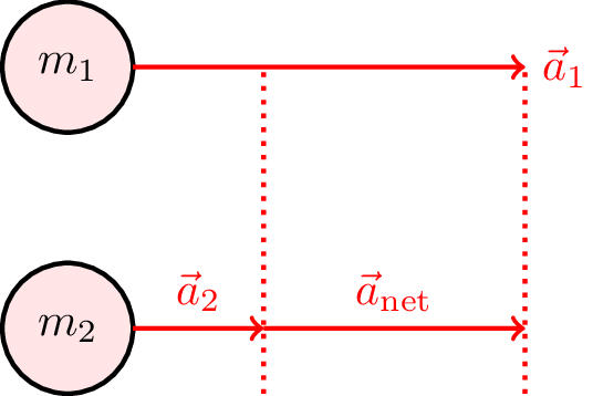
Note: previously we said that acceleration appears the same in all inertial frames. However, here we have accelerating frames, so this does not hold.
So, we have \[ \vec{a}_\text{net} = \vec{a}_1 + \frac{m_1}{m_2} \vec{a}_1 \] \[ \vec{a}_\text{net} = \left( 1 + \frac{m_1}{m_2} \right) \vec{a}_1 = \left( \frac{m_2 + m_1}{m_2} \right) \vec{a}_1 \] \[ \vec{a}_\text{net} = \left( \frac{m_2 + m_1}{m_1 m_2} \right) \underbrace{m_1 \vec{a}_1}_{\color{blue}\vec{F}_{12}} \]
In the frame of particle 2, \[ \vec{F}_{12} = \mu \vec{a}_\text{net} \] where \[ \mu = \frac{m_1 m_2}{m_1 + m_2} \] is the reduced mass.
The equation of motion of particle 1 in the non-inertial frame of particle 2 is \[ \vec{F}_{12} = \mu \vec{a}_\text{net} \] where \[ \mu = \frac{m_1 m_2}{m_1 + m_2} \] is the reduced mass.
7.2.4 Example: two beads on a spring
Consider two beads on a spring. This could, for example, be a model for diatomic molecule. This is illustrated in Figure 7.7.
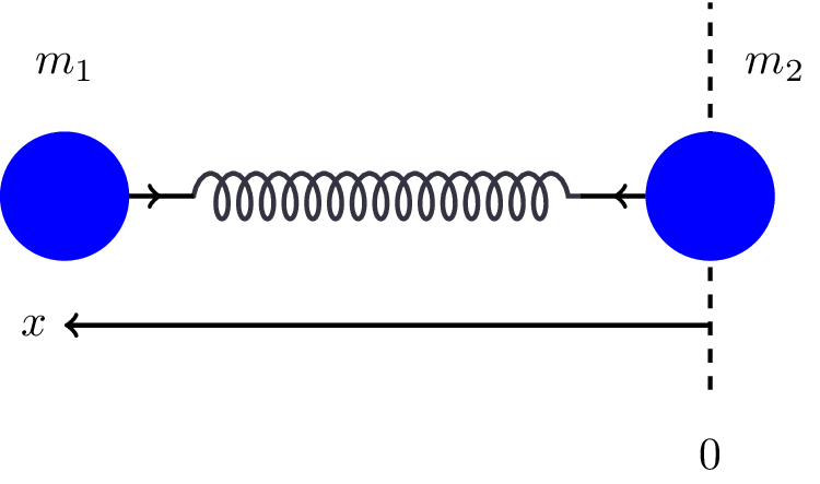
Let’s look at this motion in the frame of particle 2. In 2’s frame, 1 is moving. The acceleration is given by \[ \ddot{\vec{x}} = \vec{a}_\text{net} \]
As above, \[ \vec{F}_{12} = \mu \vec{a}_\text{net} = - k \vec{x} \] where \(k\) is the stiffness of the spring, and \(\vec{x}\) is the extension.
In 1D, \[ a_\text{net} = \ddot{x} = - \frac{k}{\mu} x \] which is the equation of motion of a simple harmonic oscillator with angular frequency \[ \omega = \sqrt{\frac{k}{\mu}} \]
This method effectively reduces the 2-body problem to a 1-body problem, in terms of relative separation, relative acceleration, and reduced mass.
Continuing the diatomic molecule analogy, let’s consider an Oxygen (O\(_2\)) molecule. Oxygen is observed to absorb infrared photons which can excite this harmonic oscillation with an angular frequency of \[\omega = 2.94 \times 10^{14} \text{ rad s}^{-1}. \]
The mass of an Oxygen atom is \(m = 2.66 \times 10^{-26} \text{ kg}\), so the reduced mass of the system is \[\mu = 1.33 \times 10^{-26} \text{ kg.}\]
The bond stiffness can then be calculated using \[ \omega = \sqrt{\frac{k}{\mu}} \] \[ k = \mu \omega^2 = 1146 \text{ N m}^{-1} \]
7.3 Composite systems
These are systems with different connected components, e.g., blocks stacked or connected to one another, or components connected by ropes.
The following examples illustrate the pairs of opposite and equal forces that arrise in composite systems in accordance with Newton’s third law.
7.3.1 Example: row of blocks
Consider a row of three blocks, each of mass \(m\), as shown in Figure 7.8.
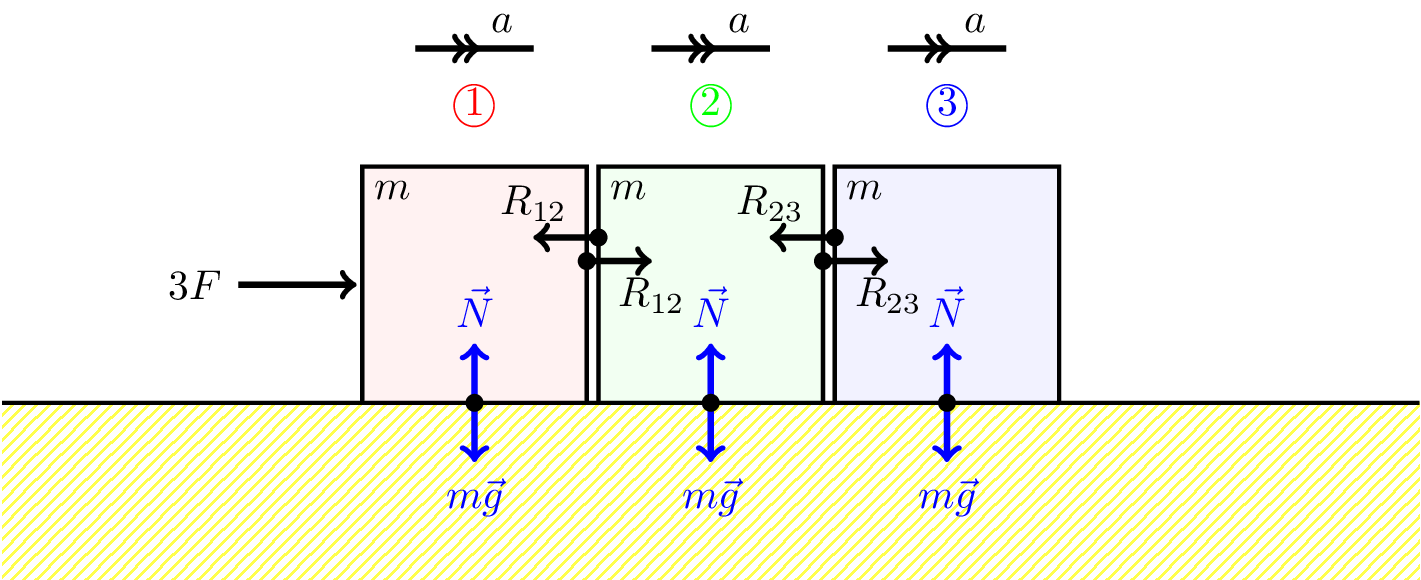
The force at the left, \(3F\), is pushing three blocks that are in contact with one another, so accelerate with the same \(a\) because they are always in contact.
- Considering all three blocks together \[ 3F = 3ma \] \[ F = ma \]
- Force on the first block is \[ 3F - R_{12} = ma \] \[ R_{12} = 2F \]
- Force on the second block is \[ R_{12} - R_{23} = ma \] \[ 2F - R_{23} = ma \] \[ R_{23} = F \]
- Force on the third block is \[ R_{23} = ma \] \[ \text{i.e., } F = ma \]
Note: if we also include friction, the force opposing the motion of each block is \(f = \mu N\). Then, considering all three blocks together, we would have \[ 3F - 3\mu N = 3ma \] or for each block individually \[ F - \mu N = a \] including friction.
7.3.2 Weights and pulleys
Another “standard” problem involved weights suspended from a pulley. This is known as an Atwood machine, as shown in Figure 7.9.
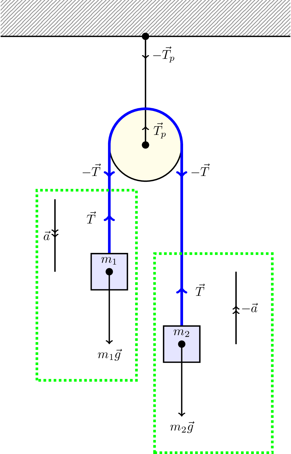
When dealing with ropes, the argument is that the tension is the same throughout, assuming the rope has noe weight, and that there are lots of balancing internal forces (in equal and opposite pairs).
Consider only the forces acting on the left-hand weight, \[ \vec{T} + m_1 \vec{g} = m_1 \vec{a} \] Similarly, for the right-hand weight, \[ \vec{T} + m_2 \vec{g} = -m_2 \vec{a} \] We can eliminate \(\vec{T}\) to get \[ \vec{a} = \left( \frac{m_1 - m_2}{m_1 + m_2} \right) \vec{g} \tag{7.1}\]
but \(\vec{T} = m_1 ( \vec{a} - \vec{g} )\) so \[ \vec{T} = m_1 \left( \frac{m_1 - m_2}{m_1 + m_2} - 1 \right) \vec{g} \] \[ = -2 \left( \frac{m_1 m_2}{m_1 + m_2} \right) \vec{g} \] \[ \vec{T} = -2 \mu \vec{g} \] where, as before, \(\mu\) is the reduced mass, \[ \mu = \frac{m_1 m_2}{m_1 + m_2} \]
7.4 Rigid bodies
When we looked at systems of particles in Section 4.2, we found that the momentum of a system of particles can be written as \[ \vec{p}_\text{tot} = M \vec{v}_\text{com} \] where \(M\) is the total mass of the system, and \(\vec{v}_\text{com}\) is the velocity of the centre of mass.
- By Newton’s first law, for an isolated system (i.e., with no external forces) momentum is conserved.
- By Newton’s third law, all particles interact by action-reaction pairs, but this does not affect the centre of mass motion.
- If an external force is applied, it will act on some or all of the particles, and cause a momentum change. We know from Newton’s second law that \[ \text{Total force } \vec{F} = M \frac{d \vec{v}_\text{com}}{dt} \] i.e., the external force accelerates the system as if acting on total mass, acting at the centre of mass.
A rigid body is then defined as an extended object of fixed shape and volume. The above analysis holds, with the constraint that the action-reaction pairs of Newton’s third law hold the particles in a rigid arrangement.
Therefore, when considering a rigid body, external forces are taken to act through the centre of mass, and cause acceleration of the total mass.
However, rigid bodies additionally may rotate about some axis. In general a force that does not act through the centre of mass will additionally lead to a rotation (see Chapter 8).
In general, motion of a rigid body will be a combination of
- motion of the centre of mass
- rotation about the centre of mass